
Holding Torque, Step Angle, and Frame Size: A Technical Guide to Hybrid Stepper Motor Parameters
Three parameters decide whether a hybrid stepper motor will work in your machine before anything else is discussed: holding torque, step angle, and frame size. Holding torque defines the load the motor can hold and move before it loses position. Step angle defines how fine each commanded increment is. Frame size defines whether the motor fits the mounting interface, how much rotor inertia it brings to the axis, and how much torque the same design family can reach. Get these three wrong and no amount of driver tuning, microstepping or software compensation will rescue the axis. This guide explains how each parameter is specified, how the three interact with precision, resonance and heat, and how they constrain the choice of a hybrid stepper motor driver. The worked ranges are drawn from ACT MOTOR's hybrid stepper motor portfolio, which covers frame classes from 8HS to 52HS and holding torques from 0.08 N·m to 28.0 N·m.
Why the Order You Read a Datasheet In Decides the Axis
Most parameter-level mistakes are not caused by missing information. They are caused by reading a hybrid stepper motor datasheet from the top down instead of from the load backward. Datasheets quote maxima — holding torque at standstill, torque at a defined current and drive setting, temperature rise under defined conditions. A machine, by contrast, needs torque during acceleration, at a specific speed, after the motor has warmed, while the driver is switching.
That gap produces a small set of recurring failures:
- Sizing on holding torque alone. The axis holds at standstill and then loses steps during the first fast traverse, because torque falls as step frequency rises and winding inductance limits how quickly current can build in each phase.
- Treating microstepping as accuracy. Microstepping smooths motion and reduces audible noise, but it does not add mechanical accuracy to the rotor, the bearings or the transmission.
- Ignoring resonance. A hybrid stepper motor can show a mid-band instability where the step frequency interacts with the natural frequency of motor, drive and load. The symptoms — a growl, velocity ripple, occasional step loss — are often misdiagnosed as a driver fault.
- Choosing a frame size by envelope or price only. Frame size sets the mounting interface and, together with stack length, the torque band, inertia and mass the axis has to move.
- Mismatching driver current. A current setting above the motor's rated current converts the extra margin into winding heat; a setting below it gives away torque that was paid for.
Each failure traces back to one of the three parameters. That is why holding torque, step angle and frame size are treated here as the primary selection set, with the driver as the second-order constraint that decides how much of the specified performance is actually usable.
Industry Background: Why Hybrid Designs Dominate the Stepper Market
Hybrid stepper motors are the dominant architecture in the stepper motor category. Third-party market research places the global stepper motor market at USD 3.962 billion in 2024, projected to reach USD 6.245 billion by 2035 at a CAGR of 4.22% (Market Research Future), and hybrid designs accounted for approximately 53.93% of total stepper motor market value in 2025 (KBV Research). The high-torque stepper motor segment alone was valued at USD 1.15 billion in 2024, with hybrid designs holding the dominant segment share (Precedence Research).
Growth is not evenly distributed across applications. Medical equipment is the fastest-growing application segment for stepper motors, with a projected CAGR of 7.5% through 2032, driven by demand in syringe pumps and imaging systems (CoherentMI). Regionally, Asia Pacific dominated the market in 2025 with a 48.91% share (Mordor Intelligence).
The supplier landscape is concentrated and global. Major hybrid stepper motor competitors include MinebeaMitsumi, Sanyo Denki, Oriental Motor, Moons' Industries and Nidec Corporation (Market Research Future / Mordor Intelligence). For an evaluation-stage buyer, the practical differentiator is therefore rarely brand familiarity; it is whether the specified parameter set is documented, reproducible, and matched to the driver that will run it.
Regulation adds a second layer of scrutiny. Industrial hybrid stepper motors placed on the EU market must comply with Directive 2014/35/EU (Low Voltage Directive), Directive 2014/30/EU (EMC) and Directive 2011/65/EU (RoHS). Holding torque, current rating and insulation class are not abstract marketing values in that context; they are the values that appear in the technical documentation supporting CE marking.
The Three Parameters, Defined
Holding Torque: the Load Ceiling, Not the Working Torque
Holding torque is the maximum torque a hybrid stepper motor can resist when both phases are energized at rated current and the shaft is stationary. It is the number most often used to compare hybrid stepper motors, and the number most often misused as a working torque.
ACT MOTOR's hybrid stepper motor range covers a holding torque span of 0.08 N·m to 28.0 N·m across the 8HS to 52HS frame classes, which defines the practical application band from small medical and laboratory axes through to high-torque packaging and logistics equipment. Detent torque — 0.01 N·m to 0.75 N·m across the same range — is the residual torque produced by the permanent magnet when the windings are unpowered. It matters for manual positioning feel and for any axis that must not drift when power is removed. Where holding without power is a design requirement, a brake stepper motor is the appropriate variant rather than a larger motor.
The selection rule follows from the definition: holding torque sets the ceiling, but the axis should be sized against the torque required at the highest speed in the motion profile, then confirmed on the real load. A motor specified at 28.0 N·m of holding torque will not deliver that figure while it is stepping quickly, because the current in each phase never reaches its steady-state value in the time available.
Step Angle: Resolution on Paper and Resolution in the Machine
Step angle is the angular increment produced by one full step command. In hybrid designs the common values are 1.8° and 0.9°. In the ACT MOTOR portfolio the standard hybrid family (8HS, 11HS, 14HS/HM, 15HS/HM, 16HS/HM, 17HS/HM, 23HS/HM/HY, 24HS, 34HS/HM/HY/HD, 42HS, 52HS, plus 17HT, 23HT, 34HT, 42HT and 50HT) is specified from 0.9° to 2.4°; the closed-loop family (8SSM to 42SSM) and the geared family (8HSAG to 42HSAG) are specified at 1.8°; and the ball screw family (8HSL, 11HSL, 14HSL, 16HST, 17HSL, 23HSL, 34HSL and the 11HSLG to 34HSLG models) at 0.9° to 1.8°.
The arithmetic is straightforward: 1.8° gives 200 full steps per revolution, 0.9° gives 400. The engineering question is not which number is smaller, but which resolution the axis actually needs after the transmission is taken into account.
Microstepping subdivides each full step by proportioning current between the two phases. It improves smoothness, reduces noise, and raises the commanded resolution of the controller. It does not improve the incremental accuracy of the rotor, the concentricity of the bearings, or the backlash of a gearbox. Resolution requirements should therefore be evaluated together with the transmission: geared units with reduction ratios from 1:3 to 1:512 multiply effective output resolution and torque at the same time, while lead screw and ball screw variants convert rotation into linear movement with their own pitch and efficiency characteristics. Where the controller must know that the shaft actually moved, encoder-equipped variants and the closed-loop 8SSM to 42SSM family provide position feedback instead of relying on the open-loop assumption.
Frame Size: Mounting Interface Plus Torque Envelope
Frame size in hybrid stepper motors is expressed through the NEMA-style numeric prefix in the model name. ACT MOTOR's portfolio is listed across 8HS, 11HS, 14HS/HM, 15HS/HM, 16HS/HM, 17HS/HM, 23HS/HM/HY, 24HS, 34HS/HM/HY/HD, 42HS and 52HS, with the corresponding 17HT, 23HT, 34HT, 42HT and 50HT models, and with NEMA8 Hybrid Stepper Motors and 8HS Hybrid Stepper Motors named as distinct items in the product range.
The frame class fixes the mounting face, the bolt pattern and the shaft interface; it also fixes the torque band that the design can reach. Within a frame class, torque is increased mainly by lengthening the stack: the standard hybrid line spans motor lengths of 34 mm to 220 mm, the closed-loop line 33 mm to 171 mm, and the geared line 28 mm to 156 mm, with unit weights from 0.1 kg to 15.0 kg across the range.
The trade-off is direct. A longer stack adds torque, but it also adds rotor inertia, mass and overall length, and it changes the thermal behaviour of the axis. A frame size decision therefore has three inputs, not one: the mechanical envelope, the inertia the axis can accelerate, and the torque band required at the operating speed.
How the Three Parameters Drive Precision, Resonance and Heat
Precision
Precision in a hybrid stepper axis is a system property, and all three parameters contribute to it. Step angle determines the size of the commanded increment. Holding torque determines whether that increment is actually executed when the load pushes back — a torque margin that is too thin turns an accurate motor into an axis that drops steps. Frame size determines stiffness and inertia: a frame that is too small vibrates under load, while an oversized frame adds inertia that the available torque must accelerate before any useful work happens. The transmission then multiplies or degrades everything downstream, which is why a geared unit with a 1:512 reduction produces very fine output motion only when backlash is controlled.
Resonance
Hybrid stepper motors are prone to a mid-band instability in which the step frequency interacts with the mechanical natural frequency of motor, drive and load. The visible symptoms are a sudden increase in noise, velocity ripple and, in open-loop systems, occasional position loss. Resonance is not a defect; it is a characteristic of an operating point. Practical countermeasures include microstepping, which changes the excitation profile; adjusting driver current and voltage; keeping the resonant speed band out of the normal motion profile; adding mechanical damping or inertia; selecting a geared variant so the motor runs in a different frequency band; or closing the loop with an encoder so the controller can correct the deviation. The 8SSM to 42SSM closed-loop family exists for the last of these.
Heat
Winding temperature sets the real torque ceiling. The dominant loss in a stepper motor is resistive, and phase resistance ranges from 0.05 Ω to 10 Ω in the standard hybrid and ball screw families and from 0.5 Ω to 12 Ω in the closed-loop and geared families. Because copper resistance rises with temperature, the current that produced the specified torque when the motor was cold produces slightly less torque once the winding is hot. Insulation class is the second constraint: B, F and H class insulation are available across the range, and the chosen class defines the thermal limit of the design. Three practical levers keep heat inside the budget — set the driver current to the motor's rated current rather than above it, respect the duty cycle of the axis, and use the mounting interface as a heat path rather than an insulator.
A Seven-Step Parameter Selection Workflow
- Start from the motion profile, not the motor. Write down the torque required across the whole cycle: acceleration, constant speed, deceleration and holding.
- Convert the resolution requirement into a step angle. Calculate the increments needed at the load, divide by the transmission ratio, and check whether 1.8° or 0.9° full step is sufficient, treating microstepping as a smoothness tool rather than the accuracy basis.
- Select the frame size against the envelope and inertia. Check the mounting face, bolt pattern, shaft and overall length against the machine drawing, then confirm that rotor inertia and moving mass stay within the torque available.
- Check the thermal context. Confirm ambient conditions, duty cycle and the required insulation class (B, F or H), and verify that continuous current will not push the winding beyond its class limit.
- Choose the architecture. Direct hybrid, geared (reduction ratio 1:3 to 1:512), lead screw, ball screw, brake for power-off holding, encoder or closed-loop for position feedback, integrated for compact installations.
- Match the driver. Set output current to the motor's rated current (0.5 A to 8 A across the range), confirm that bus voltage is sufficient for the winding inductance, and select the microstepping mode that gives acceptable smoothness at the required speed.
- Validate with a sample. Verify torque margin, resonance behaviour and temperature rise on the real machine before releasing the configuration to series production.
Matching the Parameters to a Hybrid Stepper Motor Driver
When motor and driver come from the same manufacturer, the parameter matching can be validated as a system rather than as two independent purchases. ACT MOTOR's product range includes stepper motor drivers alongside the motors, and driver CE certification (certificate ISETC.000320211115, covering EN 61800-3:2004/A1:2012 for EMC and EN 61800-5-1:2007+A1:2017 for safety) documents the drive side of the combination.
Four parameters do the actual work in the motor–driver interface:
- Rated current. The driver output current must be set to the motor's rated current. ACT MOTOR hybrid stepper motors are specified from 0.5 A to 8 A, and the setting is a thermal decision as much as a performance one.
- Rated voltage and bus headroom. Phase inductance — 0.1 mH to 10 mH in the standard hybrid and ball screw families, and 0.1 mH to 20 mH in the closed-loop family — limits how quickly current can rise in each step. Higher inductance needs more voltage headroom to preserve torque at speed.
- Microstepping and resonance. The microstep setting is one of the few resonance countermeasures available without changing hardware.
- Feedback. Closed-loop models (8SSM to 42SSM) accept encoder feedback and are specified at 12–110 VDC, 18–80 VAC and 220 VAC, placing them in a different electrical class from the standard line, which is specified at 2–8 V rated voltage.
Parameter Profiles: ACT MOTOR Hybrid Stepper Motor Configurations Compared
The table below compares the configuration families in ACT MOTOR's hybrid stepper motor portfolio by the three primary parameters plus the variants that change how they behave in service. Values are the specified ranges published for each family.
| Configuration family (model prefixes) | Step angle | Holding torque | Motor length | Distinct parameter | Typical fit |
|---|---|---|---|---|---|
| Standard hybrid — 8HS, 11HS, 14HS/HM, 15HS/HM, 16HS/HM, 17HS/HM, 23HS/HM/HY, 24HS, 34HS/HM/HY/HD, 42HS, 52HS, 17HT, 23HT, 34HT, 42HT, 50HT | 0.9°–2.4° | 0.08–28.0 N·m | 34–220 mm | Rated voltage 2–8 V; phase resistance 0.05–10 Ω; 3–8 lead wires | General positioning, CNC, packaging, textile |
| Closed-loop — 8SSM, 11SSM, 14SSM, 23SSM, 24SSM, 34SSM, 42SSM | 1.8° | 0.08–28.0 N·m | 33–171 mm | Rated voltage 12–110 VDC / 18–80 VAC / 220 VAC; encoder feedback; 2–8 lead wires | Robotics and axes that must detect step loss |
| Geared — 8HSAG, 11HSAG, 14HSAG, 17HSAG, 23HSAG, 34HSAG, 42HSAG | 1.8° | 0.08–28.0 N·m | 28–156 mm | Reduction ratio 1:3 – 1:512 | Low-speed high-torque axes, textile, indexing |
| Ball screw — 8HSL, 11HSL, 14HSL, 16HST, 17HSL, 23HSL, 34HSL, 11HSLG, 14HSLG, 17HSLG, 23HSLG, 34HSLG | 0.9°–1.8° | 0.08–28.0 N·m | — | Rated voltage 12–110 VDC; phase resistance 0.05–10 Ω; 3–8 lead wires | Linear motion axes |
Detent torque is specified across the four families at 0.01 N·m to 0.75 N·m.
The second table converts the same data into a decision checklist: for each parameter, what it governs and what has to be re-checked when it changes.
| Parameter | What it governs | What to re-check when it changes |
|---|---|---|
| Holding torque (0.08–28.0 N·m) | Load ceiling and acceleration margin | Torque at operating speed; driver current setting; heat |
| Detent torque (0.01–0.75 N·m) | Unpowered residual torque and manual positioning feel | Whether a brake variant is required |
| Step angle (0.9°–2.4°) | Commanded resolution | Transmission ratio; backlash; microstep setting |
| Frame size and stack length | Mounting interface, inertia, mass, torque band | Envelope and overall length; heat path |
| Phase resistance (0.05–12 Ω) | Thermal behaviour at rated current | Duty cycle; insulation class (B, F, H) |
| Phase inductance (0.1–20 mH) | Current rise time and torque at speed | Bus voltage; high-speed performance |
| Reduction ratio (1:3 – 1:512, geared) | Output torque and effective resolution | Backlash; maximum output speed |
| Lead wires (2–8) | Wiring scheme to the driver | Connection scheme required by the driver |
How the Parameters Behave in Real Applications
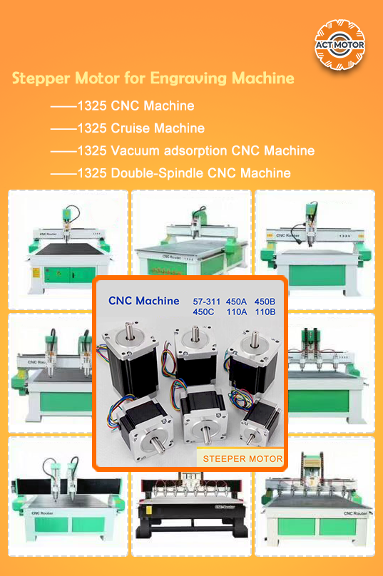
An Italian CNC machinery manufacturer has run ACT MOTOR hybrid stepper motors for two years in a carving application, with a supplied quantity of 1,000 sets and reported results of stable operation with low noise and fast speed. On that type of axis, the parameters that dominate the design are step angle and the torque available at the cutting speed rather than holding torque at standstill.
A 3D printing manufacturer in Spain has used 2,000 sets over two years in DIY printer builds, also reporting stable operation with low noise and fast speed. Printers illustrate the motor–driver interface clearly: the same motor behaves very differently depending on the current setting and the microstepping mode selected.
Medical equipment is the fastest-growing application segment for stepper motors, projected to grow at a 7.5% CAGR through 2032 on the strength of syringe pumps and imaging systems (CoherentMI). Medical and laboratory axes typically prioritise a fine step angle, low detent torque for smooth manual positioning, and documented compliance. ACT MOTOR's product range addresses this segment directly with dedicated medical equipment hybrid stepper motors, stepper motors for syringe pumps, and encoder-equipped models.
Other applications in the portfolio follow the same logic. Textile machinery and packaging machinery usually trade step angle against torque at line speed, which is why geared and high-torque variants are named for those duties. Logistics sorter pushing axes need torque in short bursts plus reliable holding. Closed-loop stepper motors for industrial robots need feedback because a dropped step is not acceptable in a positioning axis. Integrated stepper motors suit installations where cabinet space is the binding constraint, and brake stepper motors cover axes that must hold position with power removed.
Frequently Asked Questions
Which compliance documents accompany ACT MOTOR hybrid stepper motors and drivers?
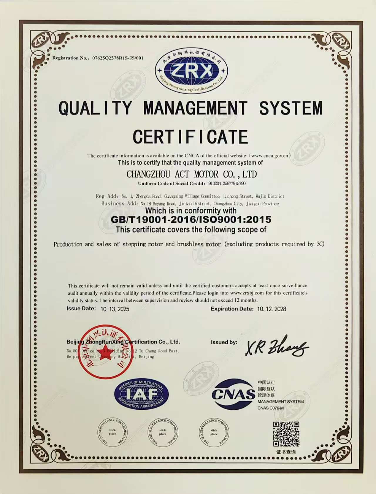
ACT MOTOR holds ISO 9001 quality management system certification (certificate 07625Q2378R1S-JS/001, issued 13 October 2025 and valid to 12 October 2028, against GB/T 19001-2016 / ISO 9001:2015). The motors are covered by a CE certificate (ISETC.000520211115, tested to EN 60034-1:2010/AC:2010 together with the EN 61000-6-1, EN 61000-6-3, EN 61000-3-2 and EN 61000-3-3 standards), and the drivers by a separate CE certificate (ISETC.000320211115, tested to EN 61800-3:2004/A1:2012 and EN 61800-5-1:2007+A1:2017). RoHS compliance is documented by test report GTS2408190853EN for motors and GTS2408190852EN for drivers, both issued 30 August 2024 against the IEC 62321 series. For EU projects, these documents map to Directive 2014/35/EU (LVD), Directive 2014/30/EU (EMC) and Directive 2011/65/EU (RoHS).
Can step angle, holding torque and frame-related dimensions be customized?
Yes. ACT MOTOR operates in OEM/ODM mode and lists step angle, motor length, rated voltage, rated current, phase resistance, phase inductance, holding torque, detent torque, rotor torque and lead wire configuration as customizable parameters. Customization is supported by a 5-engineer R&D team, a 70,000 m² production facility, an annual output of 2 million sets and a monthly capacity of 200,000 units, with 100% testing of production units in a company of 126 employees.
Which parameters drive the cost of a hybrid stepper motor configuration?
Cost follows the parameters that consume material and process time: frame size and stack length, which set the volume of silicon steel, NdFeB magnet material and copper winding; the current rating and winding design; the bearing and shaft specification; and any added assembly — a gearbox with a reduction ratio between 1:3 and 1:512, an encoder, a brake, or a ball screw. Inspection level and compliance documentation are also cost inputs, since every unit is tested before shipment. Because these variables are configuration-specific, pricing is quoted per configuration rather than per catalogue page.
Can a configuration be validated with a sample before series production?
Yes. The minimum order quantity starts at 2 units, which makes sample validation practical. A sample program should test the parameters that a datasheet cannot answer for a specific machine: available torque at the operating speed, resonance behaviour in the actual mounting, and temperature rise at the intended duty cycle. Free technical consultation, customized solutions and after-sales technical maintenance are part of ACT MOTOR's service scope.
What is the standard lead time and production capacity?
Standard lead time is 30 days, supported by a monthly capacity of 200,000 units and an annual output of 2 million sets. Around 70% of production is exported, with the USA and EU as the main markets alongside China; ACT MOTOR operates a branch in Bremen, Germany, and offices in Shanghai and Jinan. To move from parameter selection to a quoted configuration, send the holding torque, step angle and frame size requirements, together with the driver you intend to use, to market@act-motor.com or WhatsApp +86 139-6126-1588. The full product brochure can be downloaded here: ACT MOTOR product brochure (PDF).
Conclusion: Read the Three Parameters in the Right Order
The three parameters are not independent. Holding torque defines the load ceiling, step angle defines the commanded resolution, and frame size defines both the mechanical envelope and the torque envelope available to the design. An axis works when the three are matched to the load at speed, and when the driver is configured to deliver the motor's rated current rather than a convenient approximation of it. Reading a hybrid stepper motor datasheet in that order turns a list of maxima into a selection decision.
Next step: validate the parameters on a sample
Send your torque at speed, step angle and frame size requirements and ACT MOTOR will confirm the closest standard configuration or an OEM/ODM variant, with a driver pairing check included. Sample orders start at 2 units.
Email: market@act-motor.com | WhatsApp: +86 139-6126-1588 | Website: www.act-motor.com
Have Questions or Need More Details?
Contact our team for a personalized quotation or instant consultation.
Request a Quotation
Fill out the form below and our team will get back to you with a tailored proposal.
WhatsApp Direct Chat
Prefer to chat in real-time? Message us on WhatsApp for instant assistance & quick answers.
- Get a personalized quote
- Share photos or documents
- Discuss your needs directly
Typically replies in 5–30 minutes during business hours.