
How Does a Hybrid Stepper Motor Work? Rotor, Stator, and Step Angle Explained
How Does a Hybrid Stepper Motor Work? Rotor, Stator, and Step Angle Explained
Short answer: a hybrid stepper motor converts a stream of electrical pulses into fixed, repeatable angular movements. A permanently magnetised rotor — a magnet sandwiched between two toothed cups — sits inside a toothed, wound stator. Each time the driver sends a pulse, it energises the stator phases in a new pattern, and the rotor teeth rotate to the next nearest alignment point. The angular distance of that movement is the step angle. Across the hybrid stepper motor families ACT MOTOR publishes, step angles run from 0.9° to 2.4°, holding torque from 0.08 N·m to 28.0 N·m, and rated current from 0.5 A to 8 A.
This is an explainer for automation engineers and technical buyers who are new to the category and about to specify their first hybrid stepper motor — or their first non-trivial one. It covers the mechanical design (rotor and stator), why the design is called hybrid, what step angle and microstepping actually change in a positioning task, and how a Hybrid Stepper Motor Driver shapes the final result. It closes with the selection logic and the verified facts behind ACT MOTOR's hybrid range.
The Real Problem: A Stepper Motor Is Never Just a Motor
Buyers new to stepper technology usually start with one number: holding torque. Holding torque is a real specification, but it describes only one condition — windings energised, rotor stationary. It says nothing about what happens at a thousand pulses per second with a load attached, and that is exactly where most first projects run into trouble.
In practice, the positioning result comes from three parts working together:
- The motor's magnetic and mechanical design — step angle, holding torque, detent torque, rotor inertia, phase resistance and phase inductance.
- The driver — current regulation, microstep setting, supply voltage, and whether the axis runs open-loop or with encoder feedback.
- The load — friction, inertia, gravity on vertical axes, and how quickly the axis must index.
When those three are mismatched, the symptoms are consistent and easy to misread. The motor loses steps at higher speeds. An axis vibrates or buzzes at one particular speed band. The motor runs hot even at moderate load. The machine drifts quietly out of position over a shift. None of these are the motor's fault alone — all of them are matching problems between motor, driver and mechanics.
Industry Background: Why the Hybrid Design Became the Default
Market research puts the stepper motor category on a steady growth path. Market Research Future values the global stepper motor market at USD 3.962 billion in 2024 and projects USD 6.245 billion by 2035, a CAGR of 4.22%. Inside that figure, hybrid stepper motors are the dominant technology: KBV Research estimates that hybrid designs accounted for approximately 53.93% of total stepper motor market value in 2025. Mordor Intelligence places Asia Pacific at a 48.91% regional share in 2025, and CoherentMI identifies medical equipment as the fastest-growing application segment for stepper motors, with a projected CAGR of 7.5% through 2032 driven by syringe pumps and imaging systems. Precedence Research valued the high-torque stepper motor segment at USD 1.15 billion in 2024, again with hybrid designs holding the dominant segment share.
The competitive landscape is concentrated. MinebeaMitsumi, Sanyo Denki, Oriental Motor, Moons' Industries and Nidec Corporation are commonly listed among the major global players (Market Research Future / Mordor Intelligence), alongside a broad base of regional manufacturers supplying OEM and custom configurations.
Changzhou ACT Motor Co., Ltd. (ACT MOTOR) is a hybrid stepper motor and stepper driver manufacturer based in Changzhou, Jiangsu, China, founded in 2010, exporting to the USA, EU and China with a European branch in Bremen, Germany. Its range covers hybrid stepper motors, stepper motor drivers, lead screw and ball screw stepper motors, geared stepper motors and brake stepper motors, including closed-loop hybrid motors. Motors in the ACT MOTOR hybrid range cover frame sizes from 8HS and NEMA8 hybrid stepper motors up to 52HS, with the published standard family listed as 8HS, 11HS, 14HS/HM, 15HS/HM, 16HS/HM, 17HS/HM, 23HS/HM/HY, 24HS, 34HS/HM/HY/HD, 42HS, 52HS, 17HT, 23HT, 34HT, 42HT and 50HT.
Why did the hybrid design take the majority of the market? Three engineering reasons usually explain it:
- Torque density. The permanent magnet inside the rotor contributes magnetic flux that a purely reluctance-based rotor does not have, so a hybrid motor generally produces more torque from the same frame size than a simple permanent-magnet or variable-reluctance stepper.
- Detent stability. The magnet holds the rotor in a defined position even with no current applied, so the axis stays where it was left.
- Fine, repeatable steps. The toothed rotor and stator convert that flux into a small, discrete step angle, which is why hybrid motors are commonly offered at 0.9° and 1.8° as standard resolutions.
Inside a Hybrid Stepper Motor: Rotor, Stator and Two Behaviours Combined
The Stator: Toothed, Laminated and Wound
The stator is the stationary half of the motor: a stack of thin steel laminations punched into poles and wound with copper coils. In ACT MOTOR's published hybrid stepper material list, the magnetic circuit uses cold-rolled non-oriented silicon steel sheet and grain-oriented silicon steel sheet; windings use pure copper enameled wire; housings are produced in aluminium alloy (ADC12, A380) or cast iron (HT200, HT250); shafts are stainless steel or 40Cr alloy steel, running in deep-groove ball bearings made from GCr15 bearing steel. Insulation is specified across B, F and H classes, and the permanent magnets used in the assemblies are NdFeB or ferrite depending on the model.
Electrically, the stator is organised into phases, most commonly two in a hybrid stepper motor. When a phase is energised, its poles become magnetic, and the pattern of north and south poles around the stator bore shifts each time the driver changes which phases are on and in which direction.
The Rotor: One Magnet, Two Toothed Cups
The rotor is where the word hybrid comes from. It is not a simple bar magnet, and it is not a plain toothed iron core either. It is an axially magnetised permanent magnet sandwiched between two soft-iron cups, and each cup is cut with a ring of teeth. The two cups are offset from one another by half a tooth pitch, so the teeth of one cup line up with the gaps of the other.
That offset is the core of the hybrid concept. The stator effectively sees a rotor with a very fine tooth pattern — roughly twice as many usable tooth positions as a single toothed cup would provide — which is how a hybrid motor reaches step angles as small as 0.9° without an impractically large number of stator poles or an oversized rotor diameter.
Why "Hybrid": Permanent-Magnet Behaviour Plus Variable Reluctance
The rotor magnet contributes permanent-magnet (PM) behaviour. Even with the windings switched off, the magnet holds the rotor in a preferred position, which is what produces detent torque — published as 0.01 N·m to 0.75 N·m across ACT MOTOR's hybrid ranges — and what produces holding torque once the windings are energised, published as 0.08 N·m to 28.0 N·m across the same families.
The toothed geometry contributes variable-reluctance (VR) behaviour. Because both rotor and stator are toothed, the reluctance of the magnetic circuit changes sharply as the rotor turns, and the rotor is continuously pulled toward the position where the air gap is smallest. The PM effect and the VR effect act on the same rotor at the same time; that combination is the reason the design is called a hybrid stepper motor.
The practical consequence is the behaviour engineers rely on: energise the phases in sequence and the rotor advances in discrete, repeatable increments, with each increment defined by the tooth geometry rather than by a continuous control loop.
Step Angle Explained: What One Step Actually Buys You
Step angle is the angular distance the rotor moves for one complete pulse sequence from the driver. It is the resolution unit of the whole system: microstepping, gearing and screw leads are all built on top of it.
The conversion is simple arithmetic — steps per revolution = 360° ÷ step angle:
| Published step angle | Full steps per revolution (calculated) | What it means in practice |
|---|---|---|
| 2.4° | 150 | Coarser increments; suited to applications where the commanded movement is large and speed matters more than fine resolution |
| 1.8° | 200 | The most common hybrid resolution; used across standard, geared and closed-loop hybrid families |
| 0.9° | 400 | Finer increments from the same frame size; useful when mechanical reduction is undesirable |
ACT MOTOR publishes 0.9° to 2.4° across its standard hybrid families, 1.8° for its hybrid closed-loop and geared families, and 0.9° to 1.8° for the ball screw hybrid family. A 1.8° motor therefore delivers 200 full steps per revolution and a 0.9° motor delivers 400 — before any microstepping or mechanical reduction is applied.
Full Step, Half Step and Microstepping
- Full step. The driver runs the standard phase sequence and each pulse produces one full step angle. This gives the most torque per step, but the coarsest motion and the most audible step-to-step vibration.
- Half step. The driver alternates between single-phase and two-phase energisation, halving the movement per pulse. Smoother than full step, with a modest torque trade-off at the intermediate positions.
- Microstepping. The driver holds controlled current ratios in both phases at once so the rotor settles between the full-step positions. Motion becomes considerably smoother and quieter, and the commanded resolution becomes finer — but the incremental torque available at each micro-step is smaller, and the achieved position still depends on load, friction and how accurately the driver regulates current.
A useful way to hold the three ideas apart: full step and half step define the mechanical resolution of the motor, while microstepping is the driver's method of interpolating between those mechanical positions. It improves smoothness first and resolution second, and it never substitutes for torque.
Step Angle on a Linear or Geared Axis
On a linear axis, step angle is only part of the resolution equation. A lead screw or ball screw converts rotation into travel, so the positioning increment depends on both the step angle and the screw lead. A gearbox does the same job in the rotary direction, trading speed for torque and reducing the movement per step: ACT MOTOR publishes reduction ratios from 1:3 to 1:512 for its geared hybrid stepper families.
Two practical consequences follow. First, if an axis needs a very fine increment, a finer step angle is only one option — a screw with a smaller lead or a gearbox can produce the same result from a standard 1.8° motor. Second, resolution must be chosen together with speed, because mechanical reduction and finer step angles both reduce the maximum achievable speed at a given pulse rate.
The Driver Is Half the System
A hybrid stepper motor only steps as well as the driver that sequences it. The driver receives pulse and direction signals from the controller, decides which phases are energised and in which direction, and regulates the current flowing through the windings. ACT MOTOR's hybrid closed-loop family is published for 12–110 VDC, 18–80 VAC and 220 VAC supplies with rated current from 0.5 A to 8 A — a reminder that supply voltage and current rating are driver-side decisions that must be matched to the motor winding rather than chosen independently.
Three driver decisions change the outcome most:
- Current setting. Set too low, torque falls away — especially at speed — and the risk of missed steps rises. Set too high, the motor runs hotter than the application allows. The correct setting holds the required load at the required pulse rate without exceeding the motor's thermal limits inside the enclosure it actually works in.
- Microstep setting. Finer microstepping means smoother, quieter motion, at the cost of torque per micro-step and, in some systems, of maximum achievable pulse rate.
- Supply voltage. A higher bus voltage drives current into the winding more quickly against its inductance, which generally improves torque at higher step rates. Motors with high phase inductance benefit most from this.
Beyond those three settings, one architecture choice matters: whether the axis runs open-loop or with feedback. Open-loop operation relies on the motor's inherent step repeatability and needs no sensor, which is why it dominates cost-sensitive indexing tasks. A stepper motor with encoder — or a closed-loop hybrid motor — lets the driver monitor rotor position and correct it, and the intelligent load-adaptive concept goes one step further by adjusting current to the actual load instead of permanently running at the maximum setting.
Step-by-Step Breakdown: Matching a Hybrid Stepper Motor to a Real Task
The sequence below is the practical version of the theory above. It is the order in which motor, driver and mechanics should be selected; jumping straight to a torque figure is the most common source of over- or under-specified axes.
- Write down the motion profile first. Distance per index, the time allowed for that index, the accuracy that genuinely matters to the process, and the duty cycle. Everything else is derived from these four items.
- Convert the profile into pulses. Divide the required movement by the movement produced per step — taking the screw lead or gear reduction into account — then divide by the indexing time to obtain the pulse rate the driver must deliver. That pulse rate, not the holding torque, decides whether the motor is suitable.
- Read torque at that pulse rate. Stepper torque falls as speed rises, so the available torque must be compared against the real load: friction, gravity on vertical axes, the inertia of accelerating the load, plus a margin for production variation. If the margin is thin, the correction is normally mechanical — gearing or a different screw — rather than a larger motor.
- Check the resonance band. Stepper systems have speed ranges where vibration increases. Microstepping, a different current setting, or a small change in the transmission usually moves the axis out of the problem band without changing the motor.
- Choose the variant that fits the mechanics. Gearbox for low speed and high torque, lead screw or ball screw for linear movement, brake for vertical axes that must hold when power is removed, encoder or closed-loop where position confirmation is required, and integrated motor-plus-driver designs for compact machines.
- Match the driver, then validate with a sample. Confirm current rating, microstep range and supply voltage against the winding, then test the real motion profile on a real sample — not a no-load bench spin.
Where Hybrid Stepper Motors Are Used — and Why
Medical and Laboratory Equipment
Syringe pumps and similar dosing mechanisms need smooth, repeatable incremental motion rather than high continuous speed, which is why hybrid steppers with microstepping drivers are widely used in them. CoherentMI identifies medical equipment as the fastest-growing stepper motor application segment at a projected 7.5% CAGR through 2032, naming syringe pumps and imaging systems as key demand drivers. ACT MOTOR lists Medical Equipment Hybrid Stepper Motors and stepper motors for syringe pumps within its hybrid range.
Textile Machinery
Textile machinery is listed among the application industries for ACT MOTOR's hybrid stepper motors. Here the value of a stepper is repeatable open-loop positioning at a defined rate, supported by the motor's detent behaviour so the axis holds its position between indexes.
Packaging Lines and Logistics Sorting
High-torque stepper motors for automated packaging lines and the Logistics Sorter Pushing Hybrid Stepper Motor are both published product types in the range. Push, transfer and indexing mechanisms of this type depend on torque per step and on holding capability when the mechanism pauses under load.
CNC and 3D Printing
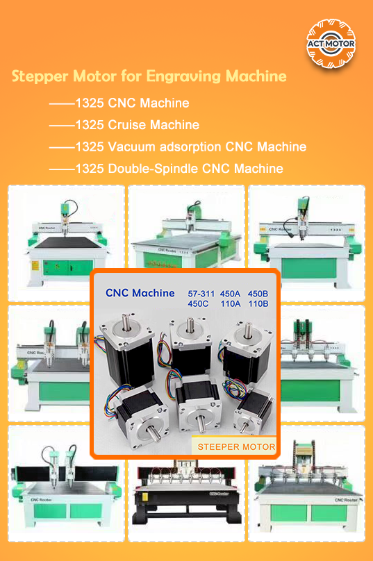
Two documented ACT MOTOR cases sit in this space. An Italian CNC machinery manufacturer ordered 1,000 sets for a carving application and reports two years of stable operation, with low noise and fast speed as the stated highlights. A Spanish 3D printing manufacturer ordered 2,000 sets for DIY equipment and likewise reports two years of stable use with low noise and fast speed.
Robotics and Precision Transmission
Closed-loop stepper motors for industrial robots and precision transmission are part of the published range, with a 1.8° step angle, 12–110 VDC / 18–80 VAC / 220 VAC supply options, 0.5 A to 8 A rated current and 2 to 8 lead wires. Where a machine must confirm that a commanded move actually happened, the encoder-based variant is the appropriate starting point.
Hybrid Stepper Motor Variants Compared (ACT MOTOR Published Data)
The comparison below uses only published ACT MOTOR hybrid stepper motor data. It is intended as a map of the range, not as a substitute for a model datasheet — the final specification should always be confirmed against the exact model being quoted.
| Variant family | Published step angle | Key published data | Typical fit |
|---|---|---|---|
| Standard hybrid 8HS, 11HS, 14HS/HM, 15HS/HM, 16HS/HM, 17HS/HM, 23HS/HM/HY, 24HS, 34HS/HM/HY/HD, 42HS, 52HS, 17HT, 23HT, 34HT, 42HT, 50HT |
0.9° – 2.4° | Motor length 34–220 mm; rated current 0.5–8 A; holding torque 0.08–28.0 N·m; detent torque 0.01–0.75 N·m; 3–8 lead wires; weight 0.1–15.0 kg | General open-loop positioning, CNC accessories, printing equipment, instrumentation |
| Hybrid closed-loop 8SSM, 11SSM, 14SSM, 23SSM, 24SSM, 34SSM, 42SSM |
1.8° | Motor length 33–171 mm; 12–110 VDC / 18–80 VAC / 220 VAC; 0.5–8 A; holding torque 0.08–28.0 N·m; 2–8 lead wires | Applications that need position confirmation, robotics and precision transmission |
| Geared hybrid 8HSAG, 11HSAG, 14HSAG, 17HSAG, 23HSAG, 34HSAG, 42HSAG |
1.8° | Motor length 28–156 mm; 12–110 VDC; 0.5–8 A; reduction ratio 1:3 to 1:512; 2–8 lead wires | Low-speed, high-torque indexing where a large mechanical advantage is required |
| Ball screw / lead screw hybrid 8HSL, 11HSL, 14HSL, 16HST, 17HSL, 23HSL, 34HSL, 11HSLG, 14HSLG, 17HSLG, 23HSLG, 34HSLG |
0.9° – 1.8° | 12–110 VDC; 0.5–8 A; phase resistance 0.05–10 Ω; phase inductance 0.1–10 mH; holding torque 0.08–28.0 N·m; 3–8 lead wires | Direct linear motion without a separate screw and coupling assembly |
Read across the table and the design logic becomes visible: the same hybrid working principle is packaged differently depending on whether the axis needs torque, feedback, reduction or linear travel. The rotor and stator behave the same way in all of them — the difference is what is attached to the shaft and how the driver is configured.
Choosing a Well-Matched Hybrid Stepper Motor: The ACT MOTOR Perspective
For a motor to be well matched, three conditions have to hold at once: the step angle suits the required increment, the torque at the required pulse rate exceeds the real load with margin, and the driver delivers current in a way the motor can sustain thermally in its actual mounting. A motor that fails any one of those conditions is not a good match, no matter how good its datasheet looks.
Changzhou ACT Motor Co., Ltd. builds its hybrid stepper motor range around that matching process. The company was founded in 2010 and operates a 70,000 m² facility in Changzhou, Jiangsu, China, integrating R&D, manufacturing and warehousing, with an annual output of 2 million sets, 126 employees, a five-engineer R&D team, and a 70% export ratio serving the USA, EU and Chinese markets from a Bremen, Germany branch supported by offices in Shanghai and Jinan.
On the supply side, published capability data for the hybrid range includes OEM/ODM production, monthly capacity of 200,000 units, a 30-day lead time, and 100% testing of motors before shipment. Customisation is offered across step angle, motor length, rated voltage, rated current, phase resistance, phase inductance, holding torque, detent torque, rotor torque and lead wires — which means a buyer with an unusual motion profile is not limited to the catalogue variants listed above.
Frequently Asked Questions
Do hybrid stepper motors need CE or RoHS documentation for the EU market?
Yes. Industrial hybrid stepper motors sold into the EU must meet the Low Voltage Directive 2014/35/EU, the EMC Directive 2014/30/EU and the RoHS Directive 2011/65/EU. ACT MOTOR holds CE certification issued by ISET, including certificate ISETC.000520211115 for motors, ISETC.000320211115 for drives and ISETC.000420211115 for power-related products, all issued on 15 November 2021 and valid until 14 November 2026. RoHS documentation includes test report GTS2408190853EN for motors and GTS2408190852EN for drivers, issued by GTS on 30 August 2024 and valid until 29 August 2029. Quality management is certified to GB/T19001-2016 / ISO9001:2015 under certificate 07625Q2378R1S-JS/001, valid until 12 October 2028.
Can a hybrid stepper motor be customised for a specific step angle, torque or shaft configuration?
Yes, within the parameters a manufacturer publishes as customisable. ACT MOTOR offers OEM/ODM production with customisation across step angle, motor length, rated voltage, rated current, phase resistance, phase inductance, holding torque, detent torque, rotor torque and lead wires. Custom work is supported by a five-engineer R&D team and, in the published purchase terms, acceptance is carried out according to the confirmed specification, drawing and sample — which is why the confirmed drawing matters as much as the motor itself.
What drives the price of a hybrid stepper motor?
Price follows the material and process content of the motor rather than the frame size alone. The main cost drivers are the volume of silicon steel laminations and copper winding in the stator, the NdFeB or ferrite magnet in the rotor, the frame size and stack length, the shaft and bearing materials, the insulation class, and whether the unit includes added functions such as an encoder, closed-loop electronics, a gearbox, a brake or an integrated screw. Compliance documentation, testing depth and order quantity also affect the commercial result, as do the agreed delivery terms — ACT MOTOR publishes delivery terms of EXW, FOB, CIF, DAP and DDP and payment before shipment.
Can I validate a hybrid stepper motor before committing to a production order?
Yes, and for a first hybrid stepper motor it is the recommended route. ACT MOTOR's stated acceptance criteria are acceptance according to the confirmed specification, drawing and sample, and the company provides free technical consultation, professional technical support and customised solutions during evaluation. A meaningful sample test runs the real motion profile — the actual pulse rate, load, microstep setting and driver current — rather than a no-load spin, because that is where mismatches appear.
What is the lead time for a hybrid stepper motor order?
ACT MOTOR publishes a 30-day lead time for its hybrid stepper motor range, supported by a monthly capacity of 200,000 units and 100% testing before shipment, with delivery terms of EXW, FOB, CIF, DAP or DDP. Buyers planning a production ramp should therefore allow for the lead time plus their own incoming validation. To discuss a specific motion profile, request a datasheet match or arrange a sample, contact the ACT MOTOR team at market@act-motor.com or +86 139-6126-1588 — the technical consultation is free of charge.
Conclusion: Match the Rotor, the Step Angle and the Driver
A hybrid stepper motor works because two behaviours are engineered onto one rotor: a permanent magnet that holds the rotor in a defined position and supplies detent and holding torque, and a toothed rotor-and-stator geometry that makes the rotor snap forward in small, repeatable increments. Step angle is simply the size of that increment — 0.9° for 400 steps per revolution, 1.8° for 200, 2.4° for 150 — and microstepping is the driver's way of smoothing the motion between those positions.
The engineer's job is therefore not to pick the largest motor, but to match three things: the step angle to the required increment, the torque at the working pulse rate to the real load, and the driver's current, microstep and voltage settings to the winding. Do that, and a hybrid stepper motor becomes one of the most predictable motion components in an automation system — which is precisely why hybrid designs hold the majority share of the stepper motor market today.
Next Step: Match Your Motion Profile to the Right Hybrid Stepper Motor
ACT MOTOR manufactures hybrid stepper motors from 8HS / NEMA8 sizes through to 52HS frames, together with stepper motor drivers, geared, brake, lead screw, ball screw, encoder and closed-loop variants. The range is ISO 9001 certified, CE marked and RoHS documented, with OEM/ODM customisation available across step angle, torque, voltage, current, resistance, inductance and lead wires.
Send your motion profile — travel per index, indexing time, load and accuracy — and the team will confirm a motor and driver match, arrange a sample, or prepare a quotation. Email market@act-motor.com, call or message +86 139-6126-1588, or download the full product catalogue: ACT MOTOR Product Catalogue (PDF). Full range details are also available at www.act-motor.com.
Have Questions or Need More Details?
Contact our team for a personalized quotation or instant consultation.
Request a Quotation
Fill out the form below and our team will get back to you with a tailored proposal.
WhatsApp Direct Chat
Prefer to chat in real-time? Message us on WhatsApp for instant assistance & quick answers.
- Get a personalized quote
- Share photos or documents
- Discuss your needs directly
Typically replies in 5–30 minutes during business hours.