
Retrofitting Hybrid Stepper Motors and Drivers into Existing Industrial Equipment: An Application Guide for Project Teams

Retrofitting a hybrid stepper motor and its driver into an existing industrial machine is a project with three failure points that appear before any hardware is ordered. The first is application mapping — matching the axis load, speed, and duty cycle to a motor specification rather than to a catalog headline. The second is mechanical fit — confirming that shaft diameter, flange pattern, and overall motor length match the original mount, or can be adapted without redesigning the axis. The third is acceptance — agreeing, in writing, on how the replacement motor and driver will be validated before a production lot is released.
This application guide addresses those points in sequence for engineers, maintenance leads, and project teams replacing a hybrid stepper motor or its driver on equipment that was originally commissioned with an earlier design. A hybrid stepper motor is a permanent-magnet/reluctance hybrid design with a toothed rotor and stator, characterised by a step angle and a holding torque, and driven by a stepper motor driver that converts pulse and direction signals into phase currents. Getting a retrofit right depends less on the motor itself than on whether the application has been translated into the right specification.
Why Retrofit Projects Fail Before Wiring Starts
The first cause is load mismatch at speed. Holding torque is measured at standstill, but an axis that must accelerate a load and then run at a target speed needs torque at that speed. A motor chosen on holding torque alone can stall or lose steps once the axis accelerates. The practical rule during a retrofit is to size the motor against the application's peak torque at its working speed, and to keep headroom for friction, belt tension, and voltage drop in the existing cabinet.
The second cause is mechanical mismatch. Frame size is only the outer envelope. Shaft diameter, shaft length, pilot diameter, flange hole pattern, and total motor length all have to be checked against the original drawing. A NEMA 23 motor from one series may not be mechanically interchangeable with a NEMA 23 motor from another series if shaft length or rear-shaft provisions differ. For linear axes, the same check applies to lead screw and ball screw stepper motors, where stroke length, lead, and end-support geometry are part of the interface.
The third cause is driver mismatch. A stepper motor driver is not a passive component; its current rating, supply voltage range, microstepping resolution, and control interface determine whether the replacement motor can deliver its rated performance. A driver rated below the motor's rated current will limit torque; a driver rated above it may overheat a smaller motor if current is not adjusted. Interface compatibility — pulse/direction, analog, or fieldbus — is the remaining factor that determines whether the retrofit can reuse the existing controller.
What Is Driving Retrofits in 2026
Third-party research places the global stepper motor market at very different values depending on what is counted. Mordor Intelligence reports USD 21.78 billion for 2026, while other research scopes arrive at materially smaller numbers because some count only the motor component and others count full motion-control systems. For a retrofit project the practical implication is that market-level figures should not drive component selection; the application's torque, speed, precision, and duty-cycle requirements should. The same source reports that hybrid stepper motors held a 49.78% share of the stepper motor market in 2025, which is consistent with the broad installed base of hybrid-driven equipment in automation, CNC, medical, textile, and packaging machinery.
Supply-side maturity also supports retrofits. Chinese exports for HS 850110 (motors with output up to 37.5 W) reached USD 2.6 billion in January–August 2026, with 11.1% going to the USA, which reflects an established supply base for small-frame motors. For project teams, that means replacement motors for a retrofit can usually be sourced faster than the equipment itself can be replaced. It also means supplier selection must be handled deliberately, because not every supplier can match an existing mount or document a custom configuration.
Changzhou ACT MOTOR Co., Ltd. is a China-based manufacturer of hybrid stepper motors, stepper motor drivers, and related motion-control components. Founded in 2010 and operating a 70,000 m² production facility with roughly 2 million sets of annual output and approximately 70% export share to the USA, EU, and China markets, ACT MOTOR is the kind of supplier a retrofit team typically evaluates when the original motor is discontinued or lead time has become unacceptable. The company holds ISO 9001:2015 certification, and its products are CE and RoHS compliant.
Mapping the Application to Motor and Driver Selection
1. Torque at the target speed
Start with the peak torque the axis must produce during acceleration, plus the running torque at the working speed. For a belt-driven axis, that includes belt pre-tension; for a vertical axis, it includes the gravity load of the carriage and tooling. ACT MOTOR's hybrid stepper motor range covers holding torque from 0.08 N·m to 28.0 N·m, which spans small laboratory stages through heavy CNC and packaging axes. When the required output torque exceeds what a direct-drive motor can deliver at the target speed, a geared stepper motor or gearbox stepper motor becomes the practical choice; ACT MOTOR's geared range offers reduction ratios from 1:3 to 1:512.
2. Positioning resolution and accuracy
Step angle determines the mechanical resolution before microstepping. ACT MOTOR hybrid stepper motors are offered with step angles from 0.9° to 2.4°, with 0.9° and 1.8° being the most common retrofit choices because they match the majority of existing controllers and mechanical ratios. When the retrofit requires closed-loop control, a stepper motor with encoder is the appropriate configuration. When the axis requires higher resolution at low speed or feedback-based stall detection, an encoder-equipped motor and a matching closed-loop driver should be specified together rather than added later.
3. Duty cycle and thermal environment
A motor sized for intermittent motion may not survive continuous operation inside a closed cabinet. For continuous duty, the motor's rated current and thermal class matter as much as holding torque. ACT MOTOR's standard range is built with B/F/H class insulation options, and the application notes for medical and laboratory equipment emphasise low heat generation and stable long-term operation as design requirements rather than optional features. If the retrofit sits in an enclosure without forced air, the supplier should be told the ambient temperature and the expected on-time ratio so the current setting can be adjusted accordingly.
4. Physical mounting envelope
The motor must fit in the space left by the original unit, which is often the constraint that eliminates otherwise-attractive candidates. ACT MOTOR's frame range covers 8HS, 11HS, 14HS/HM, 15HS/HM, 16HS/HM, 17HS/HM, 23HS/HM/HY, 24HS, 34HS/HM/HY/HD, 42HS, 52HS, 17HT, 23HT, 34HT, 42HT, and 50HT series, with motor lengths from 34 mm to 220 mm and weights from 0.1 kg to 15.0 kg. For a linear-axis retrofit, lead screw stepper motors and ball screw stepper motors replace the motor-plus-coupling-plus-screw stack with a single unit, but stroke, lead, and end-support geometry then become the mounting constraints rather than shaft diameter.
Matching the driver
Driver selection follows motor selection. The driver must be rated for the motor's rated current, its supply voltage must sit inside the existing cabinet's available DC bus, and its control interface must match the existing controller. In ACT MOTOR application records, medical peristaltic pump retrofits use the DM542 driver, CNC axes use DM542, DM860H, or DM2722 depending on frame size, and 3D printer axes use DM542 or DM420. Matching these pairings to the motor's rated current — not to the motor's frame size alone — is what prevents the two most common post-retrofit problems: torque shortfall at speed and driver overheating.
Step-by-Step Retrofit Process
- Document the existing axis. Record the original motor's frame size, shaft dimensions, flange pattern, step angle, rated current, rated voltage, and lead wire count. Record the original driver's model, current setting, supply voltage, and control interface. Photograph the mounting area, including any belt tensioner, coupling, or rear-shaft hardware. This documentation becomes the input to every later decision.
- Select the motor configuration. Match the documented axis to the motor range. For open-loop axes with adequate margin, a standard hybrid stepper motor is sufficient. For vertical or gravity-loaded axes, a brake stepper motor holds position when power is removed. For axes where output torque exceeds direct-drive capacity at the target speed, a geared stepper motor is appropriate. For axes where feedback is required by the controller, a stepper motor with encoder is specified. ACT MOTOR offers OEM/ODM customization across step angle, motor length, rated voltage, rated current, phase resistance, phase inductance, holding torque, detent torque, rotor torque, and lead wires — which is the practical route when no standard model matches the existing mount exactly.
- Select and match the driver. Choose the driver by rated current and control interface, not by frame size. Confirm the supply voltage is available in the existing cabinet, and confirm the microstepping setting the controller can support. If the retrofit uses an integrated stepper motor, the driver is inside the motor and the selection question becomes supply voltage and control interface rather than current pairing.
- Verify the mechanical interface. Before ordering, compare the CAD model or drawing of the selected motor to the original mount. Check shaft diameter, shaft length, pilot diameter, flange hole pattern, and overall length. For linear-axis replacements, check stroke, lead, and end support. If any dimension differs, decide whether a custom shaft, custom flange, or adapter is needed and confirm the supplier can provide it.
- Commission and validate. Install the motor, set driver current to the motor's rated value, and run the axis at low speed before reaching production speed. Check for lost steps by returning to a known position after a sequence of moves. Measure motor temperature at the end of a representative duty cycle. Listen for resonance at low speed and adjust microstepping or acceleration profile if needed. Confirm that the existing controller's pulse and direction signals are clean and that the cable shielding is adequate for the industrial environment.
- Agree acceptance criteria with the supplier. Before the production lot is released, agree in writing on what will be checked at receiving inspection, what the sampling plan is, and what constitutes a rejected unit. ACT MOTOR states 100% test as its quality-control policy, and the incoming inspection step on the customer side should still be defined independently — typically frame dimensions, shaft runout, winding resistance, insulation resistance, no-load current, and visual inspection of leads and connectors.

Retrofit Use Cases
The application logic described above has been applied to several industrial equipment categories. The four below show how the same motor-driver mapping decision changes with the application requirement.
Medical peristaltic pump
In a medical peristaltic pump retrofit, the axis must deliver constant torque at very low speed with minimal pulsation and low vibration, because flow-rate stability depends on smooth rotation rather than on peak torque. The application uses a DM542 driver and prioritises no-step-loss start-stop control, low heat generation, and long-term continuous operation. ACT MOTOR supplies hybrid stepper motors for syringe pumps and peristaltic pumps in this category; the selection emphasis is on step angle consistency and thermal behaviour, not on maximum holding torque.
Laboratory analyser XYZ stage
A laboratory analyser retrofit requires ultra-high positioning accuracy, ultra-low vibration, and ultra-low noise across three orthogonal axes. The application uses integrated stepper motors to reduce cabinet wiring and to keep the moving mass low, with strict temperature-rise control because the surrounding measurement environment is thermally sensitive. In this case, the retrofit decision is driven by integrated motor selection and by the mechanical alignment of the stage rather than by driver current.
CNC machine axis
A CNC retrofit is the opposite of the laboratory case. The axis is expected to carry high load with high rigidity under continuous working conditions, with anti-interference requirements that come from the spindle drive and the surrounding electrical environment. The application uses DM542, DM860H, or DM2722 drivers depending on frame size, and the motor selected must deliver its rated torque at the cutting speed, not only at standstill. ACT MOTOR has supplied a CNC machinery manufacturer in Italy with 1,000 sets for carving applications, with low noise and fast speed as the reported highlights and two years of stable operation as the outcome.
3D printer axis
A 3D printer retrofit differs again: high-precision positioning, low vibration, and no step loss at high speed are the dominant requirements, and the X/Y/Z/E axes each need a different trade-off between speed and torque. The application uses DM542 or DM420 drivers. ACT MOTOR has supplied a 3D printing manufacturer in Spain with 2,000 sets for DIY applications, again with low noise and fast speed as the highlights and two years of stable operation as the outcome.
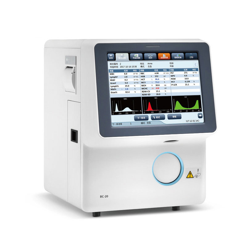
Beyond these four, the same mapping logic applies to stepper motors for textile machinery, to high-torque stepper motors for automated packaging lines, to closed-loop stepper motors for industrial robots, and to the logistics sorter pushing hybrid stepper motor used in parcel-handling equipment. The specific requirements differ, but the sequence — document the axis, select the motor, match the driver, verify the mount, commission, and agree acceptance criteria — does not.
Retrofit Configuration Comparison
The table below compares the main motor configurations used in retrofits and the specification that should be confirmed before ordering each one. It is intended as a selection checklist, not as a performance ranking.
| Configuration | Typical retrofit fit | Specification to confirm |
|---|---|---|
| Standard hybrid stepper motor | Open-loop axis with adequate torque margin at the target speed | Step angle, holding torque, frame size, rated current |
| Stepper motor with encoder | Axis where position loss or stall detection matters, or where the controller supports closed-loop control | Encoder resolution, driver encoder input, control architecture |
| Geared stepper motor / gearbox stepper motor | Output torque exceeds direct-drive capacity, or output speed must be reduced | Reduction ratio (1:3 to 1:512), backlash, output torque at target speed |
| Brake stepper motor | Vertical or gravity-loaded axis requires holding force when power is removed | Brake holding torque, brake voltage, release time |
| Ball screw stepper motor / lead screw stepper motor | Linear axis is being replaced with a self-contained actuator | Lead, stroke, axial load, critical speed, end support |
| Integrated stepper motor | Cabinet space is limited and separate driver wiring is undesirable | Supply voltage, control interface, thermal derating |
Two further configuration options appear in ACT MOTOR's portfolio and deserve mention for specialised retrofits: brake stepper motors are available in the 17HS, 23HS, and 34HS frame families, and the ball screw stepper motor range covers 8HSL, 11HSL, 14HSL, 16HST, 17HSL, 23HSL, 34HSL, 11HSLG, 14HSLG, 17HSLG, 23HSLG, and 34HSLG models. Both are selected through the same four application inputs described earlier, with the additional mechanical parameters shown in the table.

Frequently Asked Questions
What documentation does a retrofit motor need for equipment exported to the EU?
For EU-bound equipment, the retrofit motor should be accompanied by documentation that matches the actual product: a CE-related declaration or conformity documentation applicable to the motor or the machine, a RoHS declaration, and an ISO 9001:2015 quality management certificate. ACT MOTOR holds ISO 9001:2015 certification and states that its products comply with CE and RoHS. Because the compliance obligations of a component motor and a complete machine are not identical, the retrofit team should confirm with the supplier which declarations apply to the motor alone and which are the machine builder's responsibility under the applicable EU directives.
Can ACT MOTOR match a replacement motor to an existing mounting pattern?
ACT MOTOR offers OEM/ODM customization across step angle, motor length, rated voltage, rated current, phase resistance, phase inductance, holding torque, detent torque, rotor torque, and lead wires. In practice this means a retrofit team can request a modified shaft, a different lead configuration, or a different winding to suit an existing drive, rather than redesigning the axis to accept a standard model. The customisation request should include the original motor's drawing and the target electrical specification so that both the mechanical and electrical fit can be confirmed before quotation.
What drives the cost of a retrofit order?
Cost in a retrofit order is driven primarily by three factors: the frame size and holding torque class of the motor, the number of customised parameters (shaft, lead wires, winding, brake, encoder, or gearbox), and the order quantity relative to the supplier's minimum order quantity. ACT MOTOR's stated MOQ is 2 units, which is low enough for a single-machine retrofit, but the price per unit at that quantity will reflect setup rather than volume. Buyers should request a quotation that separates standard configuration, customised configuration, and tooling or setup charges, so that the comparison between suppliers is made on the same scope.
Can the project team test a sample before releasing a production batch?
Sample validation is the standard route for a retrofit, and ACT MOTOR's MOQ of 2 units supports it. The sample should be tested on the actual machine rather than on a bench, because the failure modes that matter — torque shortfall at speed, resonance, thermal rise in the cabinet, and step loss after a sequence of moves — depend on the machine's inertia, friction, and control profile. If the sample requires a custom shaft or winding, the sample should be built to the same specification as the intended production lot, otherwise the validation does not carry over.
What is the typical lead time for a retrofit order, and what should be confirmed in the purchase order?
ACT MOTOR states a lead time of 30 days and a monthly capacity of 200,000 units. For a retrofit, the purchase order should confirm four points beyond price: the exact motor specification including any customised parameter, the driver model and current setting if the driver is supplied together with the motor, the acceptance criteria at receiving inspection, and the Incoterms and delivery address. Agreeing these in writing before the order is released is what prevents the most common procurement dispute in a retrofit — a motor that meets the datasheet but not the drawing.
Request a Retrofit Sample or Technical Consultation
If the retrofit has reached the point where the axis is documented and the motor specification needs to be confirmed, ACT MOTOR accepts sample requests from 2 units and provides free technical consultation on motor-driver matching. Share the original motor drawing, the driver model, and the application requirements to receive a specification recommendation.
Contact: market@act-motor.com · Brochure: ACT MOTOR Product Brochure (PDF)
Conclusion
A successful retrofit of a hybrid stepper motor and driver into existing industrial equipment is determined by three decisions made before hardware is ordered: mapping the application to a motor and driver specification, verifying the mechanical interface against the original drawing, and agreeing acceptance criteria with the supplier. The four application inputs — torque at speed, positioning resolution, duty cycle and thermal environment, and mounting envelope — narrow the motor choice. The driver follows from the motor's rated current and the existing controller's interface. The mechanical interface is confirmed from the drawing, not from the frame size alone.
For project teams evaluating replacement motors, the practical checklist is short: document the original axis, select the configuration from the four application inputs, match the driver by rated current, verify the mount, commission at the machine, and write the acceptance criteria into the purchase order. Suppliers who can support customisation at a low minimum order quantity and document their quality system in verifiable terms make that sequence easier to close.
Have Questions or Need More Details?
Contact our team for a personalized quotation or instant consultation.
Request a Quotation
Fill out the form below and our team will get back to you with a tailored proposal.
WhatsApp Direct Chat
Prefer to chat in real-time? Message us on WhatsApp for instant assistance & quick answers.
- Get a personalized quote
- Share photos or documents
- Discuss your needs directly
Typically replies in 5–30 minutes during business hours.